
External Devices
The External Devices feature allows you to integrate PlayIt Live with third-party hardware systems for complete studio automation. This GPIO-style interface enables bidirectional communication between PlayIt Live and external equipment such as on-air lights, control buttons, telephone hybrids, transmitter controllers, and other broadcast equipment.
TECHNICAL FEATURE
External Devices is an advanced feature for broadcast engineers and technical staff familiar with serial communications, GPIO hardware, and microcontroller programming (Arduino, etc.). This feature requires the Remote Management Module. If you're unsure about hardware integration or electrical connections, consult a qualified broadcast engineer before proceeding.
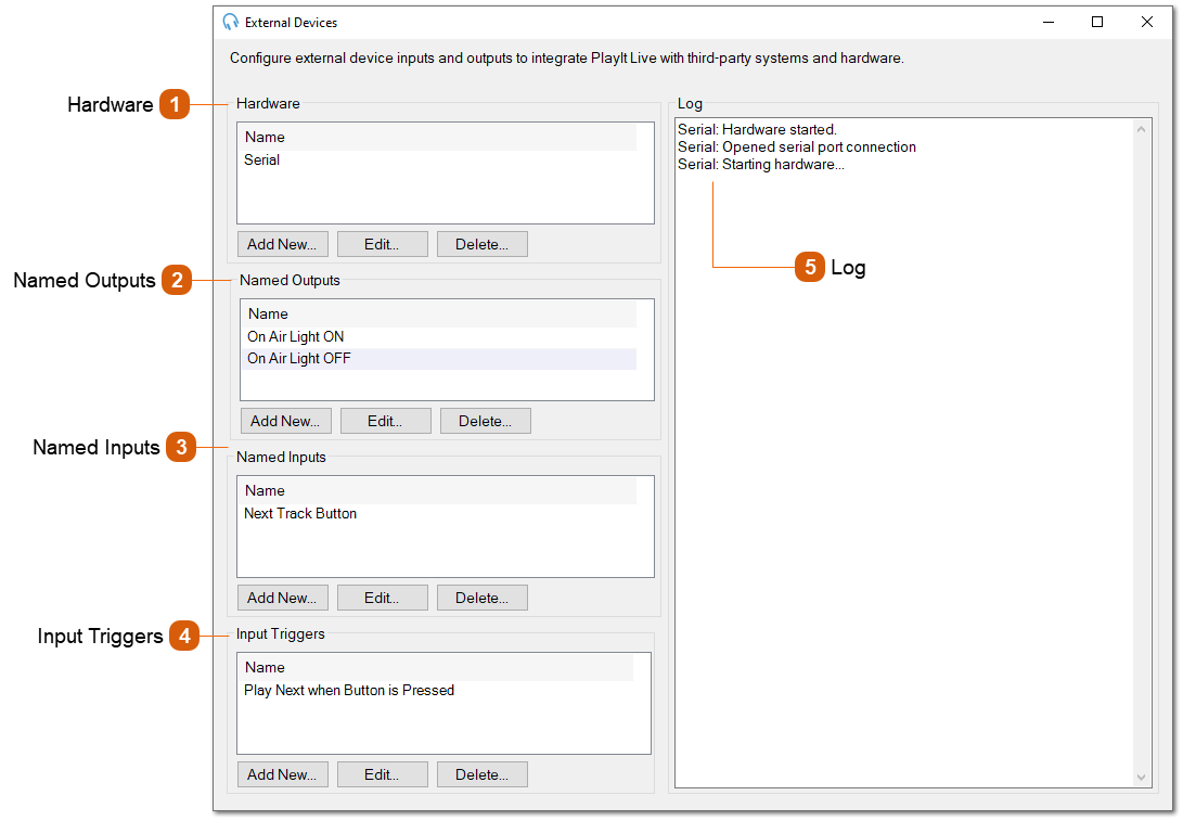
Hardware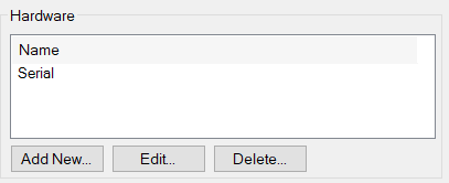 The Hardware section is where you configure the physical devices that connect to your computer. PlayIt Live supports these types of hardware interfaces:
Click Add New to configure a new hardware device. Each hardware device must be properly configured before you can create Named Outputs or Named Inputs that use it.
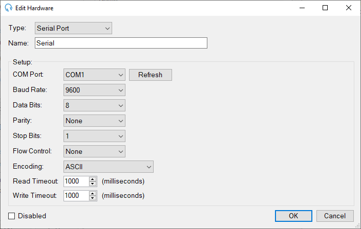 Configuring Hardware DevicesWhen you add or edit a hardware device, you'll configure its connection settings and communication parameters. The available settings depend on the hardware type you select.
General Settings
Type: Select the hardware interface type:
Name: A descriptive name for this hardware device (e.g., "Serial", "Studio Controller", "Main GPIO"). This name will appear in dropdown menus when creating Named Outputs and Named Inputs.
Disabled: Check this box to temporarily disable the hardware device without deleting its configuration. While disabled, the device will not communicate with PlayIt Live, and any Named Outputs or Inputs using this hardware will not function.
Setup (Hardware-Specific Configuration)
The Setup section contains connection parameters specific to the hardware type selected. Configuration options vary by hardware type:
Serial Port Setup
COM Port: Select the serial port your device is connected to (e.g., COM1, COM3). Click Refresh to update the list of available ports if you've just connected your device.
Baud Rate: Communication speed in bits per second. Common values are 9600, 19200, 38400, 57600, and 115200. Must match your device's configuration. Default: 9600.
Data Bits: Number of data bits per character. Typically 8 for modern devices. Options: 5, 6, 7, or 8.
Parity: Error checking method. Options: None, Odd, Even, Mark, or Space. Most devices use None.
Stop Bits: Number of stop bits signaling the end of a byte. Options: 0, 1, 1.5, or 2. Most devices use 1.
Flow Control: Hardware or software flow control for managing data transmission. Most simple devices use None.
Encoding: Character encoding for text communication. Options include ASCII, and UTF8. Default: ASCII.
Read Timeout: Maximum time (in milliseconds) to wait for incoming data before timing out. Default: 1000 ms.
Write Timeout: Maximum time (in milliseconds) to wait when sending data before timing out. Default: 1000 ms.
Broadcast Tools/Easy Driver Setup
Broadcast Tools devices use a simplified serial configuration:
COM Port: Select the serial port your Broadcast Tools device is connected to. Click Refresh to update the available ports.
Baud Rate: Communication speed. Default is 9600, which is standard for most Broadcast Tools equipment. Adjust only if your device is configured differently.
Read Timeout: Maximum time (in milliseconds) to wait for responses from the device. Default: 1000 ms.
Write Timeout: Maximum time (in milliseconds) to wait when sending commands. Default: 1000 ms.
Broadcast Tools devices typically use standardised protocols, so additional serial parameters (data bits, parity, stop bits) are pre-configured automatically.
X-Keys GPIO Setup
X-Keys USB devices connect directly via USB and require minimal configuration:
Specific Unit ID: Check this box and enter a Unit ID number if you have multiple X-Keys devices connected to the same computer. This allows PlayIt Live to target a specific device when multiple units are present. Leave unchecked if you only have one X-Keys device connected. Enable and set a unique ID (1, 2, 3, etc.) for each device when using multiple units. The Unit ID must match the ID configured on your X-Keys hardware
X-Keys devices are plug-and-play USB devices and do not require COM port or baud rate configuration.
|
Input Triggers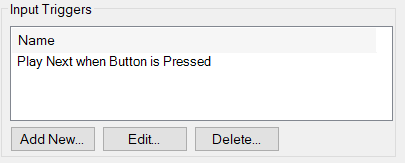 Input Triggers define what PlayIt Live should do when a Named Input is received from your external hardware. They connect incoming hardware signals to PlayIt Live automation actions, enabling physical controls and external systems to trigger specific behaviours in the software.
Overview
When your external hardware sends a command that matches a Named Input, the corresponding Input Trigger is activated and executes its configured actions. Input Triggers can perform single actions or a sequences of multiple actions.
Adding or Editing an Input Trigger
Click Add New or Edit in the Input Triggers section to configure a trigger.
 Trigger Name
A descriptive name that explains what this trigger does. This helps you identify the trigger's purpose when managing multiple triggers.
Input
Select which Named Input will activate this trigger. The dropdown shows all Named Inputs you've configured. When the selected input receives its matching command from the hardware, this trigger executes.
Trigger Actions
The list of actions that will be executed sequentially when this trigger is activated. Actions are numbered and executed in order from top to bottom. The actions available are the same as those that can be configured on scheduled events. This means any action you can schedule to occur at a specific time can also be triggered by external hardware inputs.
Disabled
Check this box to temporarily disable the trigger without deleting its configuration. While disabled, the trigger will not execute even when its associated Named Input is received. This is useful for testing or temporarily suspending automation without losing your configuration.
|
Practical Example: Controlling an On-Air Light with Arduino
This example demonstrates a complete setup for automatically controlling a studio "On Air" light using PlayIt Live's External Devices feature with an Arduino connected via USB.
Overview
In this scenario, you have an Arduino connected via USB that controls an "On Air" light (LED, relay-controlled lamp, etc.). The Arduino listens for serial commands and turns the light on or off accordingly. PlayIt Live will send commands to the Arduino at scheduled times using Scheduled Event Actions in your playout log.
Hardware Setup
-
Arduino connected to your computer via USB
-
Arduino programmed to respond to serial commands (e.g., LIGHT_ON and LIGHT_OFF)
-
On Air light connected to Arduino output pin
-
Arduino configured for 9600 baud serial communication
Step 1: Configure Hardware in PlayIt Live
-
Connect your Arduino via USB
-
Note the COM port assigned (check Device Manager)
-
Open Tools > External Devices in PlayIt Live
-
Click Add New under Hardware
-
Configure:
-
Type: Serial Port
-
Name: Arduino On Air Light
-
COM Port: Select your Arduino's COM port (e.g., COM3)
-
Baud Rate: 9600 (or match your Arduino's baud rate)
-
Data Bits: 8
-
Parity: None
-
Stop Bits: 1
-
Flow Control: None
-
Encoding: ASCII
-
Click OK
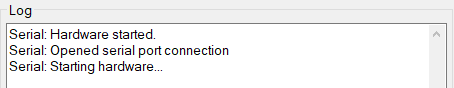
Check the Log panel for "Hardware started" and "Opened serial port connection" confirmation.
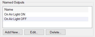
Step 2: Create Named Outputs
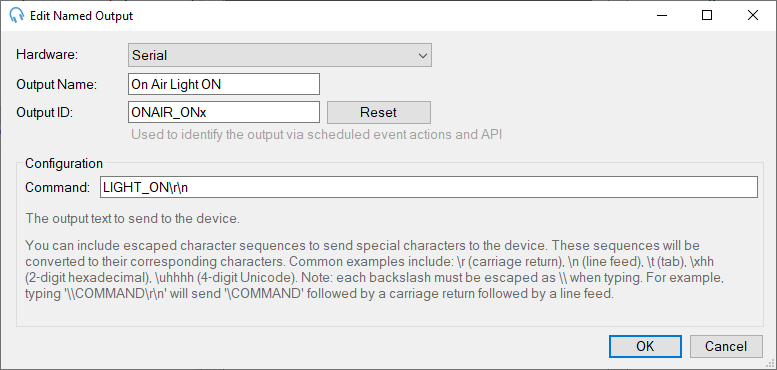
Output 1: Turn Light ON
-
Click Add New under Named Outputs
-
Configure:
-
Hardware: Arduino On Air Light
-
Output Name: On Air Light ON
-
Output ID: ONAIR_ON
-
Command: LIGHT_ON\r\n
-
Click OK
Output 2: Turn Light OFF
-
Click Add New under Named Outputs
-
Configure:
-
Hardware: Arduino On Air Light
-
Output Name: On Air Light OFF
-
Output ID: ONAIR_OFF
-
Command: LIGHT_OFF\r\n
-
Click OK
Step 3: Add Scheduled Event Actions to Your Playout Log or Scheduled Events system
You can control the light using Scheduled Event Actions in clocks and scheduled events themselves:
Using Clocks
-
Navigate to Manage > Clocks
-
Create or edit a clock for your live show (e.g., "Morning Show Clock")
-
Add a Scheduled Event Action at the start of the clock:
-
Action: Trigger Output
-
Select: On Air Light ON
-
Add your show content (music, links, etc.)
-
Add a Scheduled Event Action at the end of the clock:
-
Action: Trigger Output
-
Select: On Air Light OFF
Using Scheduled Events
-
Navigate to Manage > Scheduled Events
-
Create event: "Morning Show Start"Time: 6:00 AM (Daily)Action: Trigger Output → On Air Light ON
-
Create event: "Morning Show End"
Time: 10:00 AM (Daily)
Action: Trigger Output → On Air Light OFF
Typical Workflow
Daily Morning Show Example:
-
5:55 AM - Automation playing overnight content
-
6:00 AM - Scheduled Event Action in playout log triggers On Air Light ON
Command sent to Arduino: LIGHT_ON\r\n
Light illuminates
-
6:00 - 10:00 AM - Live show content plays
-
10:00 AM - Scheduled Event Action triggers On Air Light OFF
Command sent to Arduino: LIGHT_OFF\r\n
Light turns off
Automation resumes
Practical Example: Physical "Play Next" Button with Arduino
This example demonstrates how to use a physical button connected to an Arduino to control PlayIt Live playback. When the button is pressed, PlayIt Live will skip to the next track in the playout log.
Overview
In this scenario, an Arduino connected via USB has a physical button that sends a command to PlayIt Live when pressed. PlayIt Live receives this command as a Named Input and triggers an Input Trigger to play the next track.
Hardware Setup
-
Arduino connected to your computer via USB
-
Physical momentary pushbutton connected to Arduino
-
Arduino programmed to send serial commands when button is pressed
-
Arduino configured for 9600 baud serial communication
Step 1: Configure Hardware in PlayIt Live
-
Connect your Arduino via USB
-
Note the COM port assigned (check Device Manager)
-
Open Tools > External Devices in PlayIt Live
-
Click Add New under Hardware
-
Configure:
-
Type: Serial Port
-
Name: Studio Control Panel
-
COM Port: Select your Arduino's COM port (e.g., COM3)
-
Baud Rate: 9600 (or match your Arduino's baud rate)
-
Data Bits: 8
-
Parity: None
-
Stop Bits: 1
-
Flow Control: None
-
Encoding: ASCII
-
Click OK
Check the Log panel for "Hardware started" and "Opened serial port connection" confirmation.
Step 2: Create a Named Input
-
Click Add New under Named Inputs
-
Configure:
-
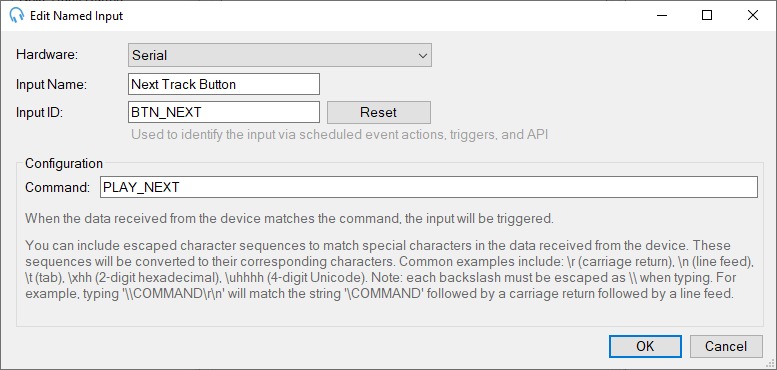
Hardware: Studio Control Panel
-
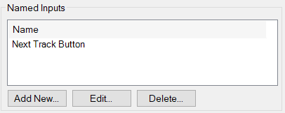
Input Name: Next Track Button
-
Input ID: BTN_NEXT
-
Command: PLAY_NEXT\r\n
-
Click OK
This input will be triggered when the Arduino sends PLAY_NEXT\r\n to PlayIt Live.
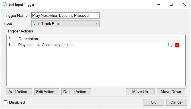
Step 3: Create an Input Trigger
-
Click Add New under Input Triggers
-
Configure:
-
Trigger Name: Play Next when Button is Pressed
-
Input: Next Track Button
-
Click Add Action...
-
Select the action: Play next Live Assist playout item (or Play next track)
-
Click OK
-
Click OK
How It Works
Complete Signal Flow:
-
Physical Action: DJ presses the button on the control panel
-
Arduino: Detects button press and sends PLAY_NEXT\r\n via serial
-
Named Input: PlayIt Live receives the command and matches it to "Next Track Button"
-
Input Trigger: "Play Next when Button is Pressed" activates
-
Action Executes: PlayIt Live plays the next item in the playout log
-
Result: Current track fades and stops and next track begins playing immediately
Practical Example: Satellite Feed Sync with Broadcast Tools Switcher
This example demonstrates how to use a Broadcast Tools ACS 8.2 Plus switcher to receive a GPI (General Purpose Input) signal from a satellite receiver, which triggers PlayIt Live to wait for the satellite feed before playing commercials.
Important Note About Broadcast Tools Support
We provide support for the External Devices feature and Named Input configuration only. We do not provide technical support for configuring, wiring, or troubleshooting Broadcast Tools hardware. For assistance with:
- Broadcast Tools unit configuration and DIP switch settings
- PIP/GPI wiring and connections
- Serial communication setup with Broadcast Tools devices
- Hardware troubleshooting
Please contact Broadcast Tools directly:
- Phone: +1 (360) 854 9559
- Email: [email protected]
- Website: www.broadcasttools.com
Refer to the Broadcast Tools ACS 8.2 Plus Installation and Operation Manual for detailed information about hardware setup, connector pinouts, and serial commands.
--
Scenario
Your station receives a syndicated program via satellite. The satellite receiver has a GPI output that sends a signal when the program ends and it's time for local commercials. You want PlayIt Live to wait for this signal before starting your commercial break.
Prerequisites
Before configuring PlayIt Live, ensure you have:
- Broadcast Tools ACS 8.2 Plus properly wired to your satellite receiver's GPI output
- Serial connection established between Broadcast Tools unit and your computer
- Broadcast Tools unit configured with appropriate Unit ID, baud rate, and PIP mode enabled
- Verified that the Broadcast Tools unit is receiving the GPI signal from your satellite receiver
If you need help with any of these prerequisites, contact Broadcast Tools support.
Step 1: Configure Hardware in PlayIt Live
-
Open External Devices in PlayIt Live
-
Click Add New under Hardware
-
Configure:
- Type: Broadcast Tools
- Name: Satellite Receiver
- COM Port: Select the appropriate port
- Baud Rate: 9600 (or match your Broadcast Tools configuration)
- Read Timeout: 1000 ms
- Write Timeout: 1000 ms
4. Click OK
Check the Log panel for connection confirmation.
Step 2: Create a Named Input
-
Click Add New under Named Inputs
-
Configure:
- Hardware: Satellite Receiver
- Input Name: Satellite Break Ready
- Input ID: SAT_BREAK
- Unit ID: Your Broadcast Tools unit ID (typically 0 or 1)
- GPI/PIP Input Number: The input number where your satellite GPI is connected (e.g., 1)
- Value Changes To: 1 or 0 depending on your GPI signal type
3. Click OK
Step 3: Create an Input Trigger for Play Next
-
Navigate to Input Triggers in the External Devices window
-
Click Add New
-
Configure:Trigger Name: Satellite Break ContinueInput: Satellite Break ReadyTrigger Actions: Click Add Action and select Play Next
-
Click OK
Step 4: Create a Clock with Timing and Automation Control
1. Navigate to Manage > Clocks
2. Create a new clock or edit an existing clock (e.g., "Satellite Show Clock")
3. Add items to your clock in this order: Clock Start (Precise Timing):
Add a Fixed Time Marker
Time: 00:00 (start of hour) or your show's start time
Type: Hard
Add a Fixed Time Marker
Time: 00:00 (start of hour) or your show's start time
Type: Hard
Switch to Manual Control:
Add a Scheduled Event Action
Action: Change Playout Mode
Mode: Automation OFF
Initial Silence (waiting for break cue):
Add a Break Note
Duration: Set to a long duration (e.g., 1800 seconds for 30 minutes)
Notes: "Satellite show playing - waiting for break cue"
Important: Ensure the Segue checkbox is unchecked (red stop sign)
Commercial Break:
Add your commercial break tracks/jingles
Ensure these have Segue checked (green arrow) for normal flow between commercials
Return to Silence:
Add another Break Note
Duration: Set to cover the remaining satellite show time (e.g., 1800 seconds)
Notes: "Satellite show resumed - local break finished"
End of Show (Return to Normal Operation):
Add a Scheduled Event Action
Action: Change Playout Mode
Mode: Automation ON
4. Save the clock
Step 5: Schedule the Clock in Your Playout Log
1. Schedule the clock at, e.g. 2:00 PM, via Manage > Clock Schedule
2. Switch Log Scheduler ON
3. At 2pm, PlayIt Live will start the clock with precise timing and proper automation control
How It Works
Complete Workflow:
-
2:00 PM - Fixed Time Marker ensures precise start time
-
Automation switches OFF - Ensures manual control and red stop signs are respected
-
First Break Note begins - PlayIt Live outputs silence
-
Satellite show plays - External satellite feed is live on-air
-
Break Note reaches end - PlayIt Live stops at red stop sign and waits
-
Satellite receiver - Detects end of program segment, activates GPI output
-
Broadcast Tools unit - Detects GPI state change, sends data to PlayIt Live
-
Named Input triggered - "Satellite Break Ready" receives the signal
-
Input Trigger activated - Executes the "Play Next" action automatically
-
Commercial break plays - Local spots air with normal segues between them
-
Return to silence - Second Break Note begins, PlayIt Live outputs silence again
-
Satellite show resumes - External satellite feed continues
-
End of show - Automation switches back ON for normal programming